Transient Loudspeaker Model with Shorting Ring
David Meeker
dmeeker@ieee.org
08Nov2015
Introduction
FEMM presently does not directly model the complete transient behavior of a loudspeaker. However, results from a series of FEMM analysis can be used to identify parameters in a nonlinear transient model. The nonlinear transient model is ultimately implemented in Simulink in the TransientLoudspeaker example.
However, the previous note did not consider a loudspeaker with a shorting ring. Shorting rings are typically composed of aluminum or copper. Their inclusion in the structure of a loudspeaker is intended to reduce AC inductance, thereby removing a distortion mechanism.
Speaker with Shorting Ring
The same loudspeaker with shorting ring considered in BlockedImpedance1kHz will also be modeled in the present note. As shown in Figure 1, a copper shorting ring around the central pole is the geometry under consideration. The dimensions of the loudspeaker are described in detail as the SSF-082 example in [1].
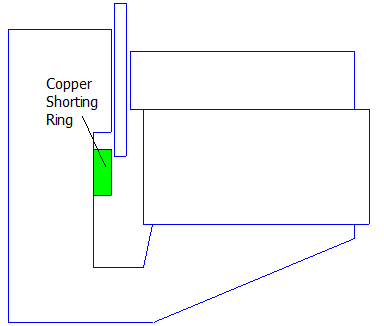
Figure 1: Loudspeaker geometry depicting shorting ring location.
Matlab Scripts
The ssf_082_vs_position_with_ring_coarse.m script does the following:
- Moves the coil of the speaker through its full range of travel, evaluating results at a number of intermediate positions
- Evaluates from -15mm to +15mm at 5mm steps
- At each position step, finds the DC inductance by evaluating an incremental AC problem (an AC problem linearized about the DC operating point established by the permanent magnet) at a frequency of 1μHz.
- At each position step, evaluates the complex-valued, frequency-dependent inductance at frequencies of 1, 10, 100, 1000, and 10000Hz.
- At each position step, evaluates the BL gain of the actuator (i.e. force per unit current in the coil).
- Fits an L/R network model (the one shown as Figure 1 in TransientLoudspeaker) that represents the frequency-dependent inductance at each position step
- Fits a function to the values of each inductance and resistance vs. position to interpolate inductance and resistance between the evaluated points
- Fits a function to the BL curve data points
- Saves the parameters describing the network inductance and resistance vs. position and BL vs. position curves.
In this case, the position dependence of the inductances and resistances in the network mode are assumed to have the form:
\(L_n(x) = \exp \left(c_0 + c_1 x + c_2 x^2 +c_3 x^3 \right) \)
where \(c_0 \ldots c_3\) are parameters that are identified so that the curve is a best-fit to finite element results. In the previous example, a cubic polynomial was used instead of the exponential of a cubic polynominal. For the geometry with the shorting ring, it was found that fitting function with better dynamic range was needed to model the interactions with the shorting ring as the coil changes position.
The SpeakerTransientModelWithRing.mdl and SpeakerTransientModelNoRing.mdl Simulink models simulate the transient behavior of the loudspeaker as driven by an arbitrary input voltage waveform. One of the outputs of the simulation is the acceleration of the loudspeaker cone. Acoustic sound pressure is proportional to the acceleration of the loudspeaker cone, so the acceleration output can be interpreted as sound pressure.
Example Results
The magnitude of the inductance with and without the ring is shown in Figures 3 and 4. At coil positions adjacent to the ring (where inductance is high at very low frequency), the ring profoundly changes inductance at higher frequencies. However, when the coil is displaced to its uppermost position, the effect of the shorting ring is largely negligible.
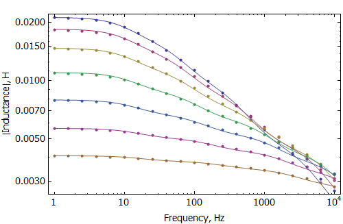
Figure 2: Inductance vs. Frequency without ring at various coil positions.
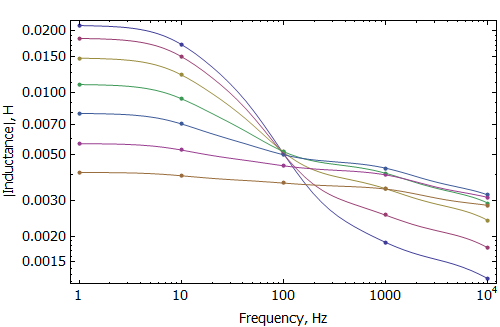
Figure 3: Inductance vs. Frequency with ring at various coil positions.
For the purposes of the example, a 40Vpk voltage at 120Hz was applied to the terminals of the loudspeaker. In this case, the high inductance (and its pretty large change over the stroke) make the voice coil oscillate around a point other than the center of the coil's stroke. The version with the ring re-centers the coil and has a bit less distortion.
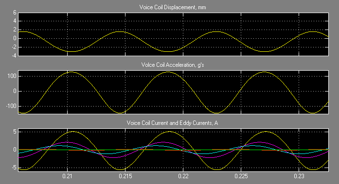
Figure 3: Simulation without shorting ring.
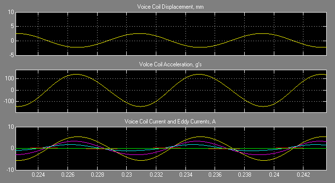
Figure 4: Simulation with shorting ring.
References
[1] L. Bortot, Optimization of demodulation rings in professional loudspeakers, Masters Thesis, University of Padua, 2012.
[2] P. Jumppanen, "Lumped parameter analysis of a dynamic loudspeaker", April 8, 2013 http://www.har-bal.com/wp-content/uploads/Speaker_theory.pdf.
| File | Last modified | Size |
|---|---|---|
| EvalInductance.m | 2016-01-12 18:14 | 288b |
| GetErr.m | 2015-11-26 13:32 | 222b |
| GetParms.m | 2015-11-26 13:32 | 1Kb |
| SpeakerTransientModelNoRing.mdl | 2015-11-26 15:28 | 43Kb |
| SpeakerTransientModelWithRing.mdl | 2015-11-26 15:28 | 43Kb |
| ssf-082.FEM | 2015-11-26 13:31 | 9Kb |
| ssf-082_vs_position_with_ring_coarse.nb | 2015-11-26 14:27 | 489Kb |
| ssf_082_vs_position_with_ring_coarse.m | 2015-11-26 13:32 | 4Kb |