Sliding Band Benchmark
The objective is to compare results without "sliding band" for a realistic motor to a sliding band with a complete (360 degree) motor model with a periodic air gap boundary condition and half a motor (180 degrees) with an anti-periodic air gap boundary condition.
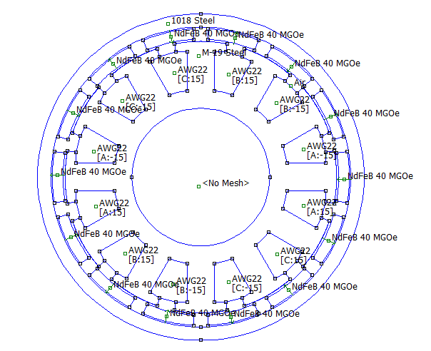
The selected motor is an outrunner "LRK" motor with 14 rotor magnets and 12 stator slots with a single-layer concentrated winding. The geometry is shown below in Figure 1.

Figure 1: Motor geometry.
The currents for the example are specified as 4A for the B phase and -4A for the C phase. The motor is well-centered to produce torque with respect to the B and C phases. An analysis of the entire motor (see WholeMotor.fem below) yields a torque of about 55.4mNm via the "Weighted Stress Tensor" (WST), the recommended method of computing torque in motor models that do not employ the a sliding band method.
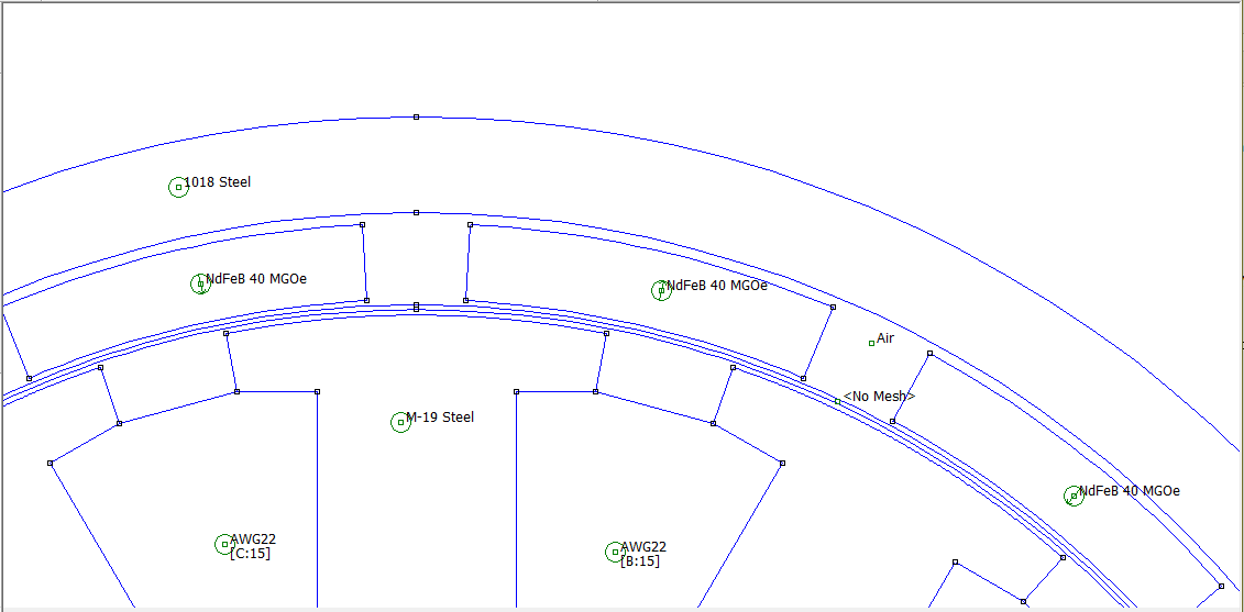
The same motor can be modeled using a sliding band. Here, the air gap is a 0.2mm (about 0.008"). Concentric circles are drawn within the gap. The circles are labeled with the periodic air gap boundary condition "myGap". The region between the circles is labeled as "<No Mesh>". A zoom-in showing the annular rings and "no mesh" definition is shown below as Figure 2:

Figure 2: Whole motor model with sliding band motion model
Analyzing this model and computing torque through the sliding band torque integral yields a result of 55.4mNm, the same as the model of the entire motor without the sliding band.
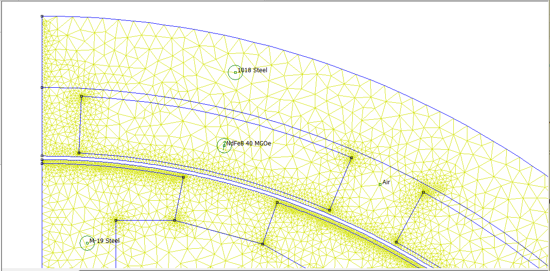
Using anti-periodic boundary conditions, this motor could be sufficiently modeled using only half of the geometry. A zoom of a sliding band version of half of the motor is shown in Figure 3.

Figure 3: Half motor model with sliding band motion model
In the half-motor model, the "cuts" in the rotor and stator are joined together using anti-periodic boundary conditions as described at: http://www.femm.info/wiki/PeriodicBoundaries. Here an anti-periodic air gap boundary condition is used instead of a periodic one, since only half the motor is modeled. When the motor is analyzed and force is computed via the sliding band torque integral, the integral again produces a result of 55.4mNm. In this case, the program can figure out that we've cut the motor in half, and the sliding mode torque computation products the torque for the entire motor. If torque is computed via WST on the same geometry, the result is half the sliding mode torque--the WST doesn't automatically figure out that only half the motor is being modeled.
A detailed comparison between torque computed using the three different models is shown below in Table 1. The computed torques computed by these different models are different by less than 0.1%. FEMM models for each different case are available in the Files section at the bottom of this page. Although WST and sliding band produce nearly the same torque result, the benefit of the sliding band is that different rotor orientations can be modeled by changing a boundary condition parameter rather than moving the rotor. The sliding band formulation avoids remeshing the motor, eliminating a source of numerical noise (i.e. remeshing), so that computed torque varies smoothly with rotor orientation.
| Whole Motor, Weighted Stress Tensor Torque | 55.4274mNm |
| Whole Motor with Sliding Band, Sliding Band Torque Integral | 55.4302mNm |
| Half Motor with Sliding Band, Sliding Band Torque Integral | 55.3843mNm |
| File | Last modified | Size |
|---|---|---|
| HalfMotorSlidingBand.fem | 2019-11-08 22:14 | 12Kb |
| HalfMotorSlidingBand.png | 2019-11-08 22:34 | 103Kb |
| WholeMotor.fem | 2019-11-08 22:14 | 17Kb |
| WholeMotor.png | 2019-11-08 22:19 | 33Kb |
| WholeMotorSlidingBand.fem | 2019-11-08 22:14 | 17Kb |
| WholeMotorSlidingBand.png | 2019-11-08 22:27 | 21Kb |