Rotor Motion using an (Anti)Periodic Air Gap Boundary Condition
David Meeker
dmeeker@ieee.org
25Feb2018
1 Introduction
As of 25Feb2018, the rotor motion model described in SlidingBand has been put into FEMM. The rotor motion model allows the rotor and stator of a rotating machine to have the same mesh regardless of the angular position of the rotor. By having the same mesh at every angle, a big source of numerical error (i.e. remeshing) is removed. Accurate forces and torques can then be obtained quickly from models with a relatively coarse mesh.
2 Air Gap Boundary Condition Description
The rotor motion model is invoked by creating a boundary condition of the "Periodic Air Gap" or "Anti-periodic Air Gap" type. As an example of the application of the boundary condition, an example brushless DC motor geometry from [1] is used. The machine model is shown below as Figure 1. Because of the structure of this machine, only one pole's worth of the machine need be modeled when anti-periodic boundary conditions are applied to its edges.
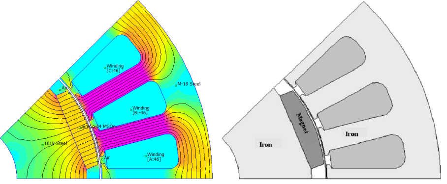
Figure 1: Machine model from Fig. 4 of [1] with its FEMM representation.
In the model, an unmeshed region is drawn in the middle of the air gap, and the (anti)periodic air gap boundary condition is applied to either side of the gap, as shown below in Figure 2. Note that in Figure 2, boundary conditions apbc1-apbc4 represent regular anti-periodic boundary conditions that are applied to periodic edges of the problem domain.
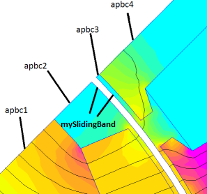
Figure 2: Detail of air gap showing application of different boundary conditions.
Figure 3 shows the Boundary Property dialog where the air gap boundary condition is defined. From the drop list, "Anti-periodic Air Gap" is selected due to the problem's anti-periodic geometry. If two poles or the entire machine were modeled instead, a "Periodic Air Gap" boundary condition would be used instead. Two other highlighted entries in Figure 3 are the "Inner Angle" and "Outer Angle" edit boxes. These edit boxes are used to define a shift between the two sides of the boundary versus the as-drawn configuration. These angles essentially define rotor motion. The Inner Angle box defines the angular displacement of the rotor (since this is an inner rotor machine), and the Outer Angle box defines the displacement of the rotor. Here, the Outer Angle is set at zero (to denote no stator motion) and the Inner Angle is set to the desired rotor orientation.
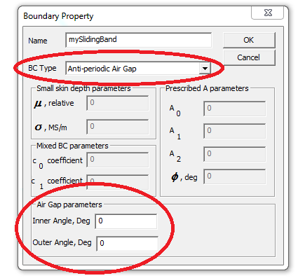
Figure 3: Detail of air gap showing application of different boundary conditions.
Internally, the program builds a stationary mesh of quadrilateral elements in the air gap. The program then uses cubic interpolation to map the nodes on surfaces defined as air gap boundary conditions onto the quadrilateral elements in the air gap. Since a high-order, continuously differentiable interpolation is used, the formulation produces smooth voltage and torque results as the rotor moves.
In the finite element results displayed on the screen, the rotor and stator do not move with respect to one another, but the solution displays the results of the change in rotor position. Since there are no changes to the problem configuration when the rotor moves, the Triangle mesh generator creates the same mesh regardless of rotor position. Since the rotor and stator mesh is the same regardless of rotor angle, remeshing is eliminated as a source of numerical error. Figure 4 below shows an animation of the solutions at 1 degree increments in rotor position to demonstrate the idea.
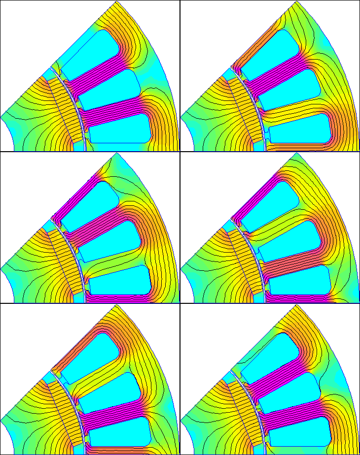
Figure 4: Air Gap Angle parameters specify rotor displacement, but rotor's position in model is unchanged.
3 Comparison to Published Benchmark
As a quantitative demonstration, the results from FEMM can be directly compared to the BLDC motor example in [1]. Unfortunately, [1] does not give a careful listing of all relevant machine parameters, but the article does have a detailed picture of the motor's cross-section and states that the air gap length is 0.7mm. Using the free ScanIt data digitizer, the detailed cross-section geometry can be gleaned from Fig. 4 of [1]. The materials and axial length were selected to yield a line-to-line voltage whose amplitude is a match to that in Fig. 5 of [1]. A detailed list of the derived dimensions and materials is shown below in Table 1.
| Attribute | Value |
| Rotor Inner Diameter | 22.8mm |
| Rotor Iron Outer Diameter | 50.5mm |
| Rotor Outer Diameter | 55.1mm |
| Magnet Width | 15.8566mm |
| Air Gap Length | 0.7mm |
| Angle Spanned by Tooth | 11.9deg |
| Tooth width | 4mm |
| Tooth Root diameter | 86.592mm |
| Stator Outer Diameter | 100mm |
| Turns/Slot | 46 |
| Winding Wire | 4X20AWG copper wire |
| Magnet Material | Sm2Co17 24MGOe |
| Stator Material | 24 Gauge M19 NGO Steel @ 98% fill |
| Rotor Material | 1018 steel |
| Axial Length | 50mm |
As in [1], the no-load line-to-line voltage was obtained using \(5 \mu s\) time steps for a machine running at 2000rpm, implying a 0.06 degree step in position. In [1], it is stated that the air gap is meshed using 0.5 degree increments, such that there are just over 8 position steps per mesh element. With these fine steps, the interaction of the motion with the mesh clearly comes into evidence.
For the FEMM simulation, the same 0.06 degree rotor position step was used. To obtain a comparably coarse mesh density, "smart meshing" was turned off, resulting in a 1977 node mesh for the entire geometry with elements in the gap spanning 0.6 degrees (yielding 10 position steps per mesh element). A close-up of the mesh is shown in Figure 5 below.
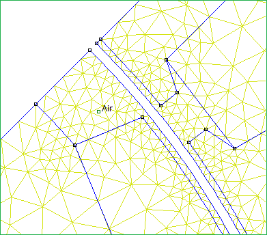
Figure 5: Mesh has 0.6 degree spacing along the air gap.
As in [1], some 2000 simulations were performed over 120 degrees of rotor motion. A list of flux linkage versus time was numerically differentiated with respect to time to yield line-to-neutral voltage. The difference between line-to-neutral voltages was taken to yield line-to-line voltage. Both a Mathematica notebook and a Matlab script performing these calculations are provided at the bottom of this page.
The simulated line-to-line voltage from FEMM (orange) superimposed on to of Fig. 5 from [1] is shown in Figure 6. The voltage is a good match to [1], but the waveform does not match in every respect due to an inexact model of the geometry from [1] and due to assumptions about material selection. It can be noted that the simulated waveform is very smooth without requiring any sort of smoothing of the data points.

Figure 6: Simulated and benchmark line-to-line voltage for a BLDC machine from [1].
A close-up of the region shown in Fig. 6 of [1] is shown here as Figure 7, superimposed on top of Fig. 6 of [1]. This is an area where the two simulations do not exactly match in amplitude. The point of the figure is that the voltage generated from FEMM is very smooth--as smooth as higher-order schemes from [1] that require extra node points located inside the moving band.
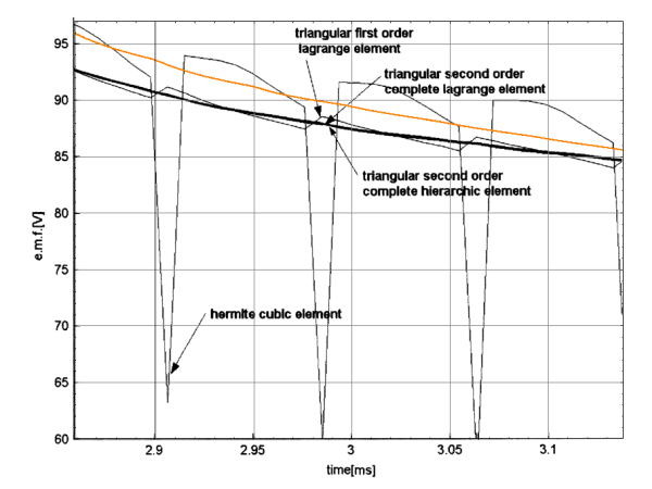
Figure 7: Detail of simulated and benchmark line-to-line voltage for a BLDC machine superimposed on Fig. 6 from [1].
Although not presented in [1], the computed cogging torque for the same simulation is also interesting. This cogging torque is shown in Figure 8. Although the mesh is coarse, the computed cogging torque is a smooth function of position.
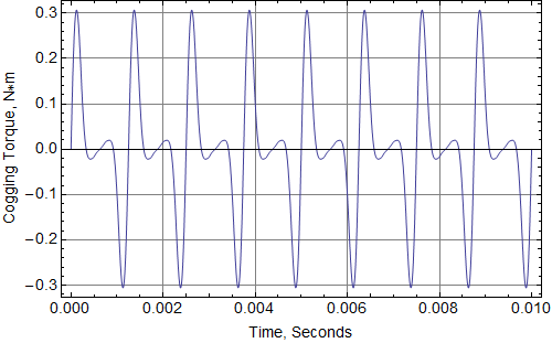
Figure 8: Cogging torque from simulation of a BLDC machine from [1].
4 Conclusions
A new model for rotor motion is included in builds 25Feb2018 and later. The motion model is implemented via a new type of boundary condition definition. The new rotor motion model permits smooth computation of torque and voltage with a relatively coarse mesh.
References
[1] O. J. Antunes, J. P. A. Bastos, and N. Sadowski, "Using high-order finite elements in problems with movement," IEEE Transactions on Magnetics, 40(2):529-532, March 2004. DOI: 10.1109/TMAG.2004.825317
| File | Last modified | Size |
|---|---|---|
| Antunes.m | 2020-05-18 19:33 | 1Kb |
| Antunes.fem | 2018-02-25 11:07 | 10Kb |
| Antunes.pdf | 2018-03-01 05:19 | 405Kb |
| Antunes.nb | 2018-02-25 14:53 | 525Kb |