Core Loss Density Derived from a Toroidal Inductor
Consider the toroidal inductor pictured in Figure 1. The inductor has \(N\) turns each carrying current \(i\); a cross-section of area \(A\), and a path length of \(l\) around the ring.
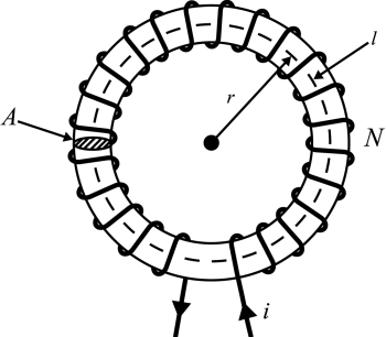
Figure 1: Toroidal inductor. We will assume that the core loss mechanism is captured by a complex-valued permeability, \(\mu\), that can be broken into real and imaginary parts as:
\[\mu = \mu_r + j \mu_i\]
The total flux, \(\Phi\), flowing around the ring can be determined by using a magnetic circuit equation:
\[ \frac{l}{\mu A} \Phi = N i \]
Solving the equation for \(\Phi\) yields:
\[ \Phi = \frac{\mu N A}{l} i \]
The inductance of the ring is then obtained by multiplying by \(N\) to get the total flux linkage of the circuit and dividing by \(i\) to get the flux linkage per unit of current:
\[ L = \frac{N \Phi}{i} = \frac{\mu N^2 A}{l} \]
The impedance of the inductor at freqency \(\omega\) is:
\[ Z = j \left( \frac{\omega \mu_r N^2 A}{l} \right) - \left( \frac{\omega \mu_i N^2 A}{l} \right) = j Z_i + Z_r \]
The impedance is composed of a real part and an imaginary part. The imaginary part, \(Z_i\), is associated with the real part of the permeability and with the usual inductive energy storage. However, the real part of the impedance, \(Z_r\), looks like resistance and is associated with losses.
If \(i\) represents the amplitude of the current (i.e. peak rather than RMS), the total power loss, \(P\), due to the real part of the impedance is:
\[P = \frac{1}{2} Z_r i^2 = - \frac{1}{2} \left( \frac{ \omega \mu_i N^2 A }{ l } \right) \left| i \right|^2 \]
To get the loss per unit volume, \(p\), the total power loss is divided by the volume of the ring, \(A\, l\):
\[p = \frac{P}{A\,l} = - \frac{1}{2} \omega \mu_i \left( \frac{N \left| i \right|}{l} \right)^2 \]
It can be noted that \(N i/l\) is the definition of field intensity, \(H\) in the ring, so that the loss per unit volume can be further simplified to:
\[p = - \frac{1}{2} \omega \mu_i \left| H \right|^2 \]
Although this loss density expression was derived from considering a toroid, the loss density expression is very general and applies on a point-by-point basis to more complicated configurations. From this expression, we can also not that \(mu_i\) must always have a negative sign to have a positive core loss.
Nonlinear AC Core Loss in FEMM
The previous loss expression in terms of \(H\) could be written in terms of \(B\) as:
\[p = - \frac{1}{2} \omega \frac{\mu_i}{|\mu|^2} \left| B \right|^2 \]
Let \(\mu\) be defined in terms of hysteresis angle \(\delta\) and magnitude \(\mu_{mag}\) that are both functions of \(B\) as:
\[ \mu(B) = \mu_{mag}(B) \left( \cos(\delta(B)) - j \sin(\delta(B)) \right) \]
Typically, hysteresis angle is relatively small such that:
\[ \sin(\delta(B)) \approx \delta(B) \]
Then, the loss expression could be written as:
\[p = \frac{1}{2} \omega \frac{\delta(B)}{\mu_{mag}(B)} \left| B \right|^2 \]
If it is assumed that hysteresis loss at a given frequency is generally proportional to \(B^2\) like in [1], the implication is that
\[\frac{\delta(B)}{\mu_{mag}} = \mbox{constant} \]
or
\[\delta(B) = \mbox{constant}* \mu_{mag} \]
References
[1] F. De Leon and A. Semlyen, "A simple representation of dynamic hysteresis losses in power transformers", IEEE Transactions on Power Delivery 10(1):315-321, Jan 1995.