Periodic Boundaries with Rotating Machines
David Meeker
09Oct2011
Introduction
With many rotating electric machines, symmetry can be employed to analyze only a fraction of the machine, rather than the entire machine. It can be especially beneficial to employ symmetry in cases where multiple analyses must be performed, e.g. characterizing the flux linkage of the motor's phases versus rotational position. The periodic boundary conditions built into FEMM allow just this sort of analysis. However, the approach to applying periodic boundary conditions to this sort of problem may not be obvious. This note demonstrates the use of periodic boundary conditions in the analysis of a permanent magnet motor as a specific example of how periodic boundary conditions can be applied in the context of the analysis of a real machine.
Machine Geometry
A 14-pole, "inside-out" brushless DC permanent magnet motor will be considered. The machine under consideration has stator with 12 slots. This is a configuration commonly employed in R/C aircraft due to its simplicity of construction and high torque density. This particular machine has a 40mm stator outer radius; a 49mm rotor outer radius; and a 45mm stack length. The machine is pictured in Figure 1.
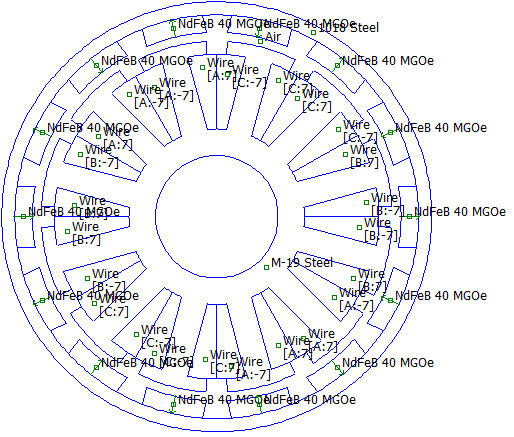
Figure 1: Example machine with 14 magnets and 12 stator slots.
In general, you can divide the number of rotor poles and stator slots by their greatest common denominator to obtain the smallest region that can be analyzed via symmetry. In this case, the greatest common denominator of 14 and 12 is 2, so the smallest piece that can be analyzed via symmetry conditions is a 7-magnet rotor and a 6-slot stator.
If the number of rotor poles to be analyzed is odd-numbered, the ends of the motor should be joined by anti-periodic (anti-symmetric) boundary conditions. If the number of rotor poles were even periodic (symmetric) boundary conditions would have been used instead.
Boundary Condition Application
The user defines the periodic or anti-periodic boundary condition type as part of the boundary condition definition. Select Periodic or Anti-periodic from the BC Type drop list to specify a symmetry or anti-symmetry boundary condition, as shown in Figure 2.
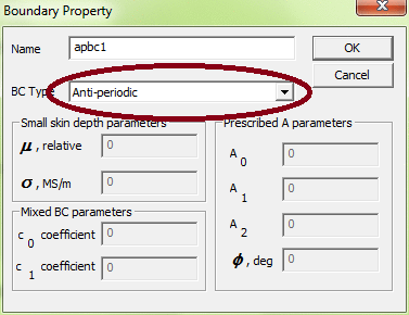
Figure 2: Boundary condition dialog box.
The way that boundary conditions have been implemented in FEMM, a particular periodic boundary condition is meant to be defined to two and only two matching line segments or arc segments. When a rotating machine is sectioned, there are usually several segments or line segments that must be joined up. This particular model has been cut so that six anti-periodic boundary conditions are needed. Figure 3 shows which of the six defined anti-periodic boundary conditions are defined to which line/arc segments on the split.
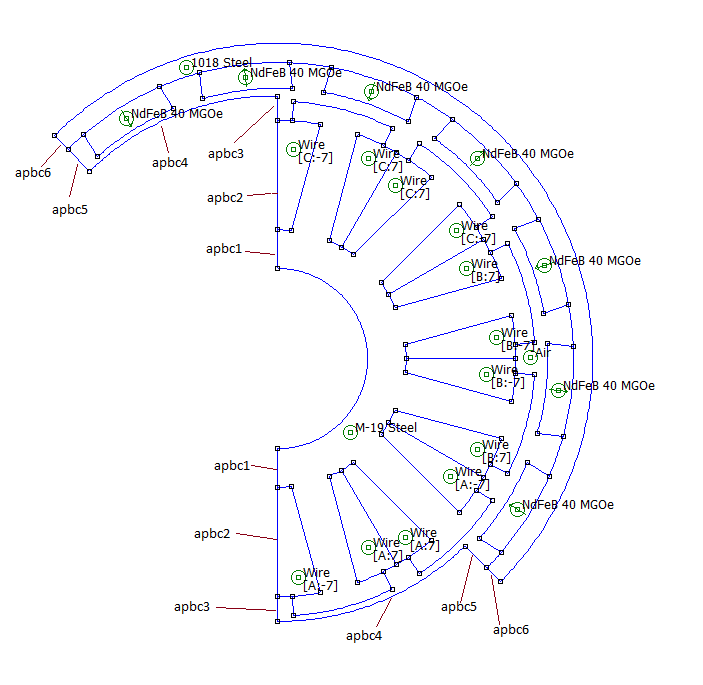
Figure 3: Application of anti-periodic boundary conditions to the split machine.
Special Treatment of the Air Gap
To make it easier to rotate the rotor and allow different positions to be analyzed, it is first recommended that all elements of the rotor be marked with the same Group number (e.g. mark all stator components as Group 1 and all rotor components as Group 2.) Then, it is recommended that a version of the model be made with two nodes defined mid-gap so that the rotor and stator are not quite connected, as shown in Figure 4. Then, when analysis at any particular angle is desired, the following steps are performed:
- Rotate rotor through angle θ.
- Draw arc segments connecting the nearly-coincident mid-gap points. The arc length spanned by these segments should be θ.
- Apply periodic boundary conditions to the newly drawn arc segments.
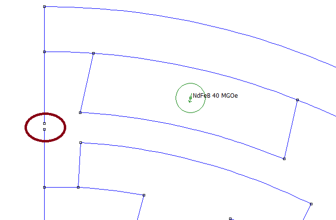
Figure 4: Close-up of geometry definition in the air gap at the split.
Solution to Example Problem
An example solution is shown in Figure 5. As can be seen in the solution, the flux lines travel across the boundaries marked as antiperiodic. Flux enters and leaves the rotor in the same way as when the entire machine is modeled. The only care that must be taken is that results such as torque, flux linkage, etc., must be multiplied by the number of analyzed segments in the complete machine (e.g. these results must be multiplied a factor of 2 for the present example to get results for the entire machine). Alternatively, the length of the machine could be scaled by the number of segments to make this correction automatically.

Figure 4: Solution with rotor turned through 45o.
Automation of Analysis
The process of turning the rotor and drawing the angle-appropriate boundary conditions is relatively straightforward. An example Matlab script is presented below. Often, such motors are Y-connected, such that under normal conditions, equal opposite currents flow in two of the three phases and no current flows in the third phase. The torque under this condition will be assessed over a range of rotor angles via the script. The example script requires the FEMM model split_lrk.fem.
n=90; % number of steps to be evaluated per wavelength of the machine
dtta=360/7/n; % number of degrees spanned by each step
deg=pi/180; % conversion from degrees to radians
tq=[]; % define an empty variable to hold torque results
q=[]; % define an empty variable to hold the angle associated with each torque result
r1=20.4; % radial location of the node defined on the stator side of the air gap
r0=20.5; % radius of the middle of the air gap
r2=20.6; % radial location of the node defined on the rotor side of the air gap
iphase=10; % phase current
openfemm;
for k=1:n
tta=k*dtta;
opendocument('split_lrk.fem');
mi_modifycircprop('A',1,iphase);
mi_modifycircprop('B',1,-iphase);
mi_modifycircprop('C',1,0);
mi_selectgroup(2);
mi_moverotate(0,0,tta);
mi_addarc(0,r1,-r2*sin(tta*deg),r2*cos(tta*deg),tta,1);
mi_addarc(0,-r1,r2*sin(tta*deg),-r2*cos(tta*deg),tta,1);
mi_selectarcsegment(-r0*sin(tta*deg/2),r0*cos(tta*deg/2));
mi_selectarcsegment(r0*sin(tta*deg/2),-r0*cos(tta*deg/2));
mi_setarcsegmentprop(1,'apbc4',0,2);
mi_clearselected;
mi_saveas('temp.fem');
mi_analyze(1);
mi_loadsolution;
mo_groupselectblock(2);
tq=[tq,2*mo_blockintegral(22)/iphase];
q=[q,tta];
mo_close;
mi_close;
end
closefemm;
plot(q,tq);
xlabel('Angle, Degrees');
ylabel('Torque, N*m');
title('Torque vs. Angle for a 1A Current');
The resulting plot of torque versus angle is shown in Figure 5. This particular machine has a sinusoidal force vs. position curve. Although a trapezoidal back-EMF is desired for brushless DC motors, sensorless BLDC motor controllers will also work well on sinusoidal motors.
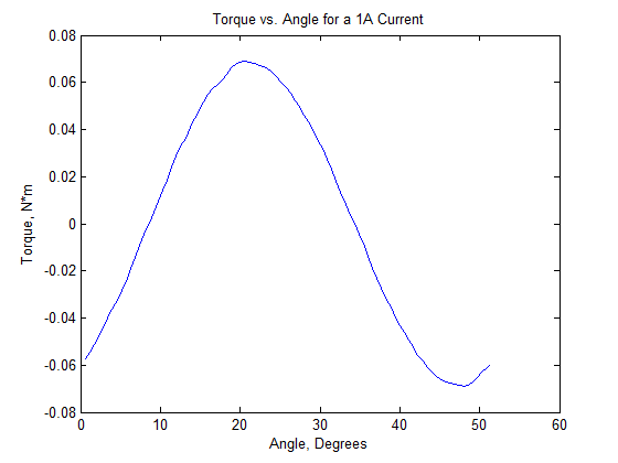
Figure 5: Torque/Current versus position.
A best-fit to the fundamental pictured in Figure 5 yields an amplitude of 0.0682 N*m/A. Typically, a BLDC motor would be run so that these two phases are energized over a range of +/-30o from the peak. The average over this region is 0.0652 N*m/A.
A typical quantity of merit for BLDC motors in model A/C applications is the Kv, the unloaded RPM/V of the motor. It can be noted that the torque constant, 0.0652 N*m/A, can also be written in units of V/(rad/s). The Kv rating of the motor is simply the inverse of the torque constant, scaled to units of RPM/V:
0.0652 N*m/A = 0.0652 V/(rad/s) = 0.0652 V/(rad/s) * 2π rad/rev * min/60s = 0.00683 V/RPM
Kv = 1/(0.00683 V/RPM) = 146 RPM/V
Conclusions
An example has been presented demonstrating the use of periodic boundary conditions in the analysis of a rotating machine. Through the use of periodic boundary conditions, the time needed to analyze a rotating machine can be significantly reduced. Although the present example only reduced the solution effort by about 1/2, the savings could be much greater with other sorts of machines (e.g. generators attached to wind turbines).